


Phase shifting transformers
Description
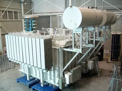
Phase Shifting Transformers Today's large electrical high-voltage transmission systems have to provide reliable and efficient electrical energy to the customer. Due to de-regulation of the market, existing systems are often stressed to the limit. According to the laws of physics, power will flow through the system using the path with the lowest impedance. Technically and economically, this is not always the most optimal path. To ensure an optimal and reliable operation of the grid, the need for power flow control becomes evident. Applications The use of phase shifting transformers (PSTs) can help to manage power flow problems resulting from complex parallel transmission paths and system inter-ties by controlling the real power flow. The variation of the in-phase voltage magnitude controls the reactive power flow through a line, whereas the phase angle variation controls the real power flow. PSTs can be built to provide a discrete phase angle shift or continuous variable phase angle shift. Some designs allow for magnitude as well as phase angle control. PSTs can be manufactured with many different winding configurations, depending on the rated voltage, the power throughput, the maximum required phase angle and whether or not voltage control is required. Discrete PSTs provide settings for a plus-or-minus fixed degree value and zero shift. If a variable phase-shift is desired, an OLTC will be installed. OLTCs are used to provide several tap positions for in principle any desired phase angle range. Basic principle When power flows between two systems, there is a voltage drop and a phase shift between the source and the load that depends upon the magnitude and power factor of the load current. If the systems are connected together with two or more parallel lines, any difference in the individual line impedances will cause unbalanced loading of the lines. By installing a PST in one of the parallel lines, an additional voltage phase angle increase or decrease can be introduced in this line. This additional phase angle will bring the power flow between the parallel lines more in balance. How a PST is designed strongly depends on the throughput power in combination with the required phase angle, the system voltage and the system short circuit power. In general, PSTs can be designed as a single core or two core design in one or more tanks. PSTs can have a direct or indirect regulation. 700 MVA, 240kV , ±30º in ±16 steps PST The required phase angle and impedance of the PST is normally based on a secure system study. Based on this study, the most optimal PST design solution can be defined in cooperation with the PST manufacturer. The figure shows a circuit with indirect regulation with an intermediate circuit arrangement. It illustrates very clearly how the phase-angle between the voltages of the source and load systems can be varied by the OLTC position. Various other circuit arrangements have been implemented. Circuit diagram, winding connections and phasor diagram of a two tank, two core design phase shifting transformer. Benefits Improved operational performance and grid reliability. Energy savings by optimizing the power flow in the electrical system. Dramatically lower costs than most FACTs devices. Reliable, long lasting power transformers technology.

، پالیترا")


")
")

